Wiring a Siren, Strobe or Sounder
Most wired alarm system installations have a an audible siren that activates in the home when an intrusion is detected. You can connect your wired siren to the Konnected device using the relay included in our kit or with a relay purchased separately (see our buying guide for suggestions).
A relay switch is a device that’s used to switch on/off a higher-voltage device with a signal from a lower-voltage device. In this case, most alarm system sirens operate at 12V DC while the NodeMCU board powering the Konnected device operates at 3.3V DC.
Identify Siren Wires
Most alarm system audible sounders simply have two wires leading to them for power, usually labeled ALARM OUTPUT
or BELL. When power is delivered, the siren activates. We’re going to wire power to the siren through the relay
switch, so that when the relay activates, current passes through the relay to activate the siren.
First, decide which output pin on the Konnected device you’re going to use to control the sounder. We
recommend pin D8 in most installations.
When Replacing an Existing Alarm Panel
If you’re replacing an existing alarm panel, look for the siren wires connected to two screw terminals on your alarm panel. Disconnect the wire leading to the positive alarm output terminal (usually red), but leave the negative (ground) wire connected to the ground terminal of the alarm panel.
Which Relay do You Have?
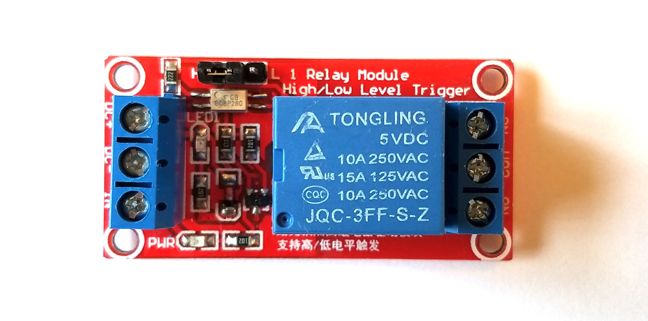
UPDATE: Beginning mid-August 2017, we started shipping our DIY kits with 5V relay modules. These relay modules are smaller, easier to mount, and have a power status LED. They work just as well as the 3V relays that we shipped with kits prior.
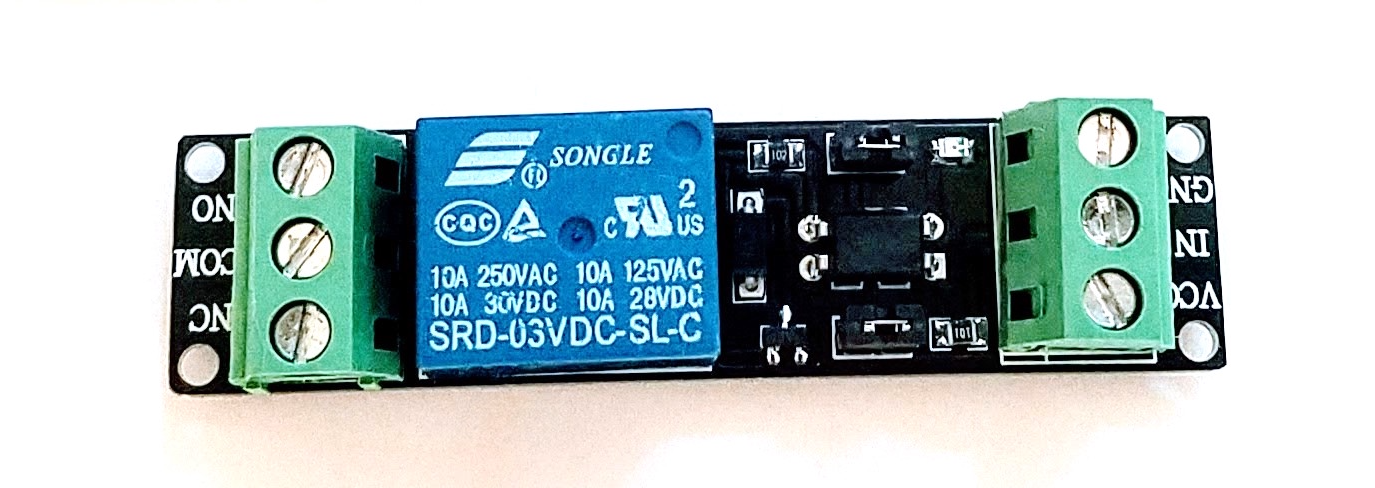
Click on the relay module that looks like yours for wiring illustrations
3V High Level Trigger Relay Module
These 3V relays work off of the 3.3V power delivered by the NodeMCU board. These relays were included in Konnected DIY kits before mid-August 2017. They’re also available on Amazon individually or in a 5-pack.
5V High/Low Level Trigger Relay Module
We’ve tested these 5V relay modules and started including them in kits shipped in mid August 2017 and later. These relays require 5V power from the NodeMCU base, so you must power the device at the base (not by USB) for the relay to work.
For this application, keep the jumper setting on for high level trigger (it’s shipped in this configuration). These are also available on Amazon in a 5-pack.
 |
 |
|---|---|
| Variant 1 with screw terminals (available on Amazon) | Variant 2 with pins (imported) |
Relay and Siren Connections
| Relay terminal | Connect to |
|---|---|
VCC |
3V or 5V pin on the Konnected board, depending on the relay voltage |
IN |
The output pin for the alarm |
GND |
Any GND pin adjacent to the 3V or 5V pin used for VCC (depending on your relay voltage) |
NO |
Postitive (red) wire leading to siren |
COM |
Aux power out (+) on the alarm panel |
NC |
Not used |
Without an Existing Alarm Panel
Without an existing alarm panel, use a 12V DC power adapter to power the Konnected device, then we can draw power from the Konnected board to also power the siren.
Connect the negative or ground wire leading to the siren to a GND pin on the bottom left of the Konnected board
(near the power adapter plug and U1 pins).
Make the following connections to the relay:
| Relay terminal | Connect to |
|---|---|
VCC |
3V or 5V pin on the Konnected board, depending on the relay voltage |
IN |
The output pin for the alarm |
GND |
Any GND pin adjacent to the 3V or 5V pin used for VCC (depending on your relay voltage) |
NO |
Postitive (red) wire leading to siren |
COM |
Any U1 pin on the Konnected board |
NC |
Not used |
4-wire Sounders with Existing Alarm Panel
More common in the U.K., some alarm system sounders will have four wires leading from the sounder to the alarm panel
terminals labeled TRG, TR-, H/O- and H/O+. In this case, leave all four wires attached to the alarm panel as-is,
and make the following additional connections using the relay:
| Relay terminal | Connect to |
|---|---|
VCC |
3V or 5V pin on the Konnected board, depending on the relay voltage |
IN |
The output pin for the alarm |
GND |
Any GND pin adjacent to the 3V or 5V pin used for VCC (depending on your relay voltage) |
NO |
TRG- on the alarm panel |
COM |
H/O- on the alarm panel |
NC |
Not used |
Output Pins
The following pins on the Konnected device can be used for outputs:
D1D2D5D6D7D8- High level trigger relay modules only

